- 您现在的位置:买卖IC网 > Sheet目录855 > CM21X5R106K06AL (AVX Corporation)CAP CER 10UF 4V 10% X5R 0805
�� �
�
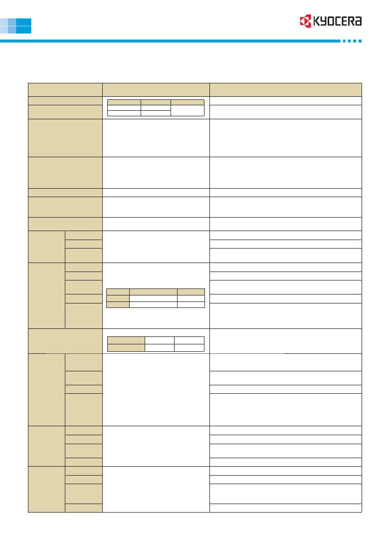
�Multilayer� Ceramic� Chip� Capacitors�
�Test� Conditions� and� Standards�
�Test� Conditions� and� Specifications� for� Temperature� Compensation� Type� (C� Δ� to� U� Δ� ?� SL� Characteristics)�
�CM/ CT/ CF� Series�
�Test� Items�
�Test� Conditions�
�Specifications�
�Capacitance� Value� (C)�
�Q�
�Capacitance� Frequency�
�C� ≤� 1000pF� 1MHz� ±� 10%�
�C� >� 1000pF� 1kHz� ±� 10%�
�Volt�
�0.5� to� 5Vrms�
�Within� tolerance�
�C� ≥� 30pF� :� Q� ≥� 1000�
�C<30pF� :� Q� ≥� 400� +� 20C�
�Measured� after� the� rated� voltage� is� applied� for� 1�
�minute� at� room� ambient.�
�Insulation� Resistance� (IR)�
�Dielectric� Resistance�
�Appearance�
�Termination� Strength�
�Bending� Strength�
�For� the� rated� voltage� of� over� 630V,� apply� 500V�
�for� 1� minute� at� room� ambient.�
�The� charge� and� discharge� current� of� the� capacitor�
�must� not� exceed� 50mA.�
�Apply� 3� times� of� the� rated� voltage� for� 1� to� 5� seconds.�
�Apply� 1.5� times� when� the� rated� voltage� is� 250V� or� over.�
�Apply� 1.2� times� when� the� rated� voltage� is� 630V� or� over.�
�The� charge� and� discharge� current� of� the� capacitor�
�must� not� exceed� 50mA.�
�Microscope�
�Apply� a� sideward� force� of� 500g� (5N)� to� a� PCB-�
�mounted� sample.� Apply� 2N� for� 0201,� and� 1N� for�
�01005� size.�
�Glass� epoxy� PCB:� Fulcrum� spacing:� 90mm,� duration�
�time� 10� seconds.�
�Over� 10000M� Ω� or� 500M� Ω� ?� μ� F,� whichever� is� less�
�No� problem� observed�
�No� problem� observed�
�No� problem� observed�
�No� significant� damage� at� 1mm� bent�
�Vibration�
�Test�
�Soldering�
�Heat�
�Resistance�
�Appearance�
�Δ� C�
�Q�
�Appearance�
�Δ� C�
�Q�
�Vibration� frequency:� 10� to� 55� (Hz)�
�Amplitude:� 1.5mm�
�Sweeping� condition:� 10� →� 55� →� 10Hz/� 1� minute� in� X,�
�Y� and� Z�
�Directions:� 2� hours� each,� 6� hours� total.�
�Soak� the� sample� in� 260� °� C� ±� 5� °� C� solder� for� 10� ±� 0.5�
�seconds� and� place� in� room� ambient,� and� measure�
�after� 24� ±� 2� hours.�
�(Pre-heating� conditions)�
�Order� Temperature� Time�
�No� problem� observed�
�Within� Tolerance�
�C� ≥� 30pF� :� Q� ≥� 1000�
�C<30pF� :� Q� ≥� 400� +� 20C�
�No� problem� observed�
�Within� ±� 2.5%� or� ±� 0.25pF,� whichever� is� larger�
�C� ≥� 30pF� :� Q� ≥� 1000�
�C<30pF� :� Q� ≥� 400� +� 20C�
�IR�
�1�
�2�
�80� to� 100� °� C�
�150� to� 200� °� C�
�2� minutes�
�2� minutes�
�Over� 10000M� Ω� or� 500M� Ω� ?� μ� F� whichever� is� less�
�Withstanding� The� charge� and� discharge� current� of� the� capacitor�
�Voltage� must� not� exceed� 50mA� for� IR� and� withstanding�
�voltage� measurement.�
�Soaking� condition�
�Resist� without� problem�
�Solderablity�
�Sn-3Ag-0.5Cu�
�Sn63� Solder�
�245� ±� 5� °� C�
�235� ±� 5� °� C�
�3� ±� 0.5� sec.�
�2� ±� 0.5� sec.�
�Solder� coverage� :� 90%� min.�
�Temperature�
�Cycle�
�Appearance�
�Δ� C�
�Q�
�IR�
�(Cycle)�
�Room� temperature� (3min.)� →�
�Lowest� operation� temperature� (30min.)� →�
�Room� temperature� (3min.)� →�
�Highest� operation� temperature(30min.)�
�No� problem� observed�
�Within� ±� 2.5%� or� ±� 0.25pF,� whichever� is� larger�
�C� ≥� 30pF� :� Q� ≥� 1000�
�C<30pF� :� Q� ≥� 400� +� 20C�
�Over� 10000M� Ω� or� 500M� Ω� ?� μ� F,� whichever� is� less�
�After� 5� cycles,� measure� after� 24� ±� 2� hours.�
�Withstanding�
�Voltage�
�The� charge� and� discharge� current� of� the� capacitor�
�must� not� exceed� 50mA� for� IR� and� withstanding�
�voltage� measurement.�
�Resist� without� problem�
�Load�
�Humidity�
�Test�
�(Except� CF�
�Series)�
�High-�
�Temperature�
�with� Loading�
�Appearance�
�Δ� C�
�Q�
�IR�
�Appearance�
�Δ� C�
�Q�
�IR�
�After� applying� rated� voltage� for� 500� +� 12/� ?� 0� hours�
�in� pre-condition� at� 40� °� C� ±� 2� °� C,� humidity� 90� to�
�95%RH,� allow� parts� to� stabilize� for� 24� ±� 2� hours,� at�
�room� temperature� before� measurement.�
�The� charge� and� discharge� current� of� the� capacitor�
�must� not� exceed� 50mA� for� IR� measurement.�
�After� applying� twice� the� rated� voltage� at� the�
�temperature� of� 125� ±� 3� °� C� for� 1000� +� 12/� ?� 0� hours,�
�measure� the� sample� after� 24� ±� 2� hours.�
�Apply� 1.5� times� when� the� rated� voltage� is� 250V� or� over.�
�Apply� 1.2� times� when� the� rated� voltage� is� 630V� or� over.�
�The� charge� and� discharge� current� of� the� capacitor�
�must� not� exceed� 50mA� for� IR� measurement.�
�No� problem� observed�
�Within� ±� 7.5%� or� ±� 0.75pF,� whichever� is� larger�
�C� ≥� 30pF� :� Q� ≥� 200�
�C<30pF� :� Q� ≥� 100� +� 10C/� 3�
�Over� 500M� Ω� or� 25M� Ω� ?� μ� F,� whichever� is� less�
�No� problem� observed.�
�Within� ±� 3%� or� ±� 0.3pF,� whichever� is� larger�
�C� ≥� 30pF� :� Q� ≥� 350�
�10pF<C<30pF� :� Q� ≥� 275� +� 5C/� 2�
�C<10pF� :� Q� ≥� 200� +� 10C�
�Over� 1000M� Ω� or� 50M� Ω� ?� μ� F,� whichever� is� less�
�Please� ask� for� individual� specification� for� the� hatched� range� in� previous� chart.�
�发布紧急采购,3分钟左右您将得到回复。
相关PDF资料
CM453232-680KL
INDUCTOR CHIP 68UH 10% 1812 SMD
CMH322522-R82ML
INDUCTOR 820NH 450MA SMD
CMR05F101JODR
CAP MICA 100PF 500V 5% RADIAL
CR-1025/BN
BATTERY LITHIUM COIN 3V 10MM
CR-1220/HFN
BATTERY LITHIUM COIN 3V PC PINS
CR-123APA/1B
BATT 3V LITH CAMERA - RETAIL PKG
CR-1612/BN
BATTERY LITHIUM COIN 3V 16MM
CR-1616/F2N
BATTERY LITHIUM COIN 3V W/TAB
相关代理商/技术参数
CM21X5R106K06AT
制造商:AVX Corporation 功能描述:MLCC 0805 X5R 10U 6.3V 10% 制造商:Kyocera 功能描述:6.3V 10uF }10% 2012
CM21X5R106K10AT
制造商:AVX Corporation 功能描述:MLCC 0805 X5R 10UF 10V +-10%
CM21X5R106K16AT
制造商:AVX Corporation 功能描述:MLCC 0805 X5R10U 16V 10% 制造商:KYOCERA Corporation 功能描述:
CM21X5R106M06AT
制造商:AVX Corporation 功能描述:CHIP CAPACITOR
CM21X5R225K06AT
制造商:AVX Corporation 功能描述:
CM21X5R225K10AT
制造商:AVX Corporation 功能描述:MLCC 0805 X5R 2.2uF 10% 10VDC
CM21X5R225K16AB
制造商:Kyocera 功能描述:16V 2.2uF }10% 2.0~1.2~1.25mm X5R +85 -55 2.0mm 1.2mm 1.25mm Cut Tape 制造商:Kyocera 功能描述:Cap Ceramic 2.2uF 16V X5R 10% SMD 0805 85°C Bulk
CM21X5R225K25AT
制造商:AVX Corporation 功能描述:MLCC 2.2UF X5R 25V 10% 0805